Saturday, August 15, 2009

Evolution Of Computer

1. First Generation (1939-1954) - vacuum tube

  • 1937 - John V. Atanasoff designed the first digital electronic computer
  • 1939 - Atanasoff and Clifford Berry demonstrate in Nov. the ABC prototype
  • 1941 - Konrad Zuse in Germany developed in secret the Z3
  • 1943 - In Britain, the Colossus was designed in secret at Bletchley Park to decode German messages
  • 1944 - Howard Aiken developed the Harvard Mark I mechanical computer for the Navy
  • 1945 - John W. Mauchly and J. Presper Eckert built ENIAC at U of PA for the U.S. Army
  • 1946 - Mauchly and Eckert start Electronic Control Co., received grant from National Bureau of Standards to build a ENIAC-type computer with magnetic tape input/output, renamed UNIVAC in 1947 but run out of money, formed in Dec. 1947 the new company Eckert-Mauchly Computer Corporation (EMCC).
  • 1948 - Howard Aiken developed the Harvard Mark III electronic computer with 5000 tubes
  • 1948 - U of Manchester in Britain developed the SSEM Baby electronic computer with CRT memory
  • 1949 - Mauchly and Eckert in March successfully tested the BINAC stored-program computer for Northrop Aircraft, with mercury delay line memory and a primitive magentic tape drive; Remington Rand bought EMCC Feb. 1950 and provided funds to finish UNIVAC
  • 1950- Commander William C. Norris led Engineer ing Research Associates to develop the Atlas, based on the secret code-breaking computers used by the Navy in WWII; the Atlas was 38 feet long, 20 feet wide, and used 2700 vacuum tubes
  • 1951 - S. A. Lebedev developed the MESM computer in Russia
  • 1951 - Remington Rand successfully tested UNIVAC March 30, 1951, and announced to the public its sale to the Census Bureau June 14, 1951, the first commercial computer to feature a magnetic tape storage system, the eight UNISERVO tape drives that stood separate from the CPU and control console on the other side of a garage-size room. Each tape drive was six feet high and three feet wide, used 1/2-inch metal tape of nickel-plated bronze 1200 feet long, recorded data on eight channels at 100 inches per second with a transfer rate of 7,200 characters per second. The comp

    lete UNIVAC system weighed 29,000 pounds, included 5200 vacuum tubes, and an offline typewriter-printer UNIPRINTER with an attached metal tape drive. Later, a punched card-to-tape machine was added to read IBM 80-column and Remington Rand 90-column cards.
  • 1952 - Remington Rand bought the ERA in Dec. 1951 and combined the UNIVAC product line in 1952: the ERA 1101 computer became the UNIVAC 1101. The UNIVAC I was used in November to calculate the presidential election returns and successfully predict the winner, although it was not trusted by the TV networks who refused to use the prediction.
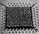
  • 1954 - The SAGE aircraft-warning system was the largest vacuum tube computer system ever built. It began in 1954 at MIT's Lincoln Lab with funding from the Air Force. The first of 23 Direction Centers went online in Nov. 1956, and the last in 1962. Each Center had two 55,000-tube computers built by IBM, MIT, AND Bell Labs. The 275-ton computers known as "Clyde" were based on Jay Forrester's Whirlwind I and had magnetic core memory, magentic drum and magnetic tape storage. The Centers were connected by an early network, and pioneered development of the modem and graphics display.

2.Second Generation Computers (1954 -1959) - transistor

  • 1950 - National Bureau of Standards (NBS) introduced its Standards Eastern Automatic Computer (SEAC) with 10,000 newly developed germanium diodes in its logic circuits, and the first magnetic disk drive designed by Jacob Rabinow
  • 1953 - Tom Watson, Jr., led IBM to introduce the model 604 computer, its first with transistors, that became the basis of the model 608 of 1957, the first solid-state computer for the commercial market. Transistors were expensive at first, cost $8 vs. $.75 for a vacuum tube. But Watson was impressed with the new transistor radios and gave them to his engineers to study. IBM also developed the 650 Magnetic Drum Calculator, the first by IBM to use magnetic drum memory rather punched cards, and began shipment of the 701 scientific "Defense Calculator" that was the first of the Model 700 line that dominated main frame computers for the next decade
  • 1955 - IBM introduced the 702 business computer; Watson on the cover of Time magazine March 28
  • 1956 - Bendix G-15A small business computer sold for only $45,000, designed by Harry Huskey of NBS
  • 1959 - General Electric Corporation delivered its Electronic Recording Machine Accounting (ERMA) computing system to the Bank of America in California; based on a design by SRI, the ERMA system employed Magnetic Ink Character Recognition (MICR) as the means to capture data from the checks and introduced automation in banking that continued with ATM machines in 1974.

3. Third Generation Computers (1959 -1971) - IC

  • 1959 - Jack Kilby of Texas Instruments patented the first integrated circuit in Feb. 1959; Kilby had made his first germanium IC in Oct. 1958; Robert Noyce at Fairchild used planar process to make connections of components within a silicon IC in early 1959; the first commercial product using IC was the hearing aid in Dec. 1963; General Instrument made LSI chip (100+ components) for Hammond organs 1968
  • 1964 - IBM produced SABRE, the first airline reservation tracking system for American Airlines; IBM announced the System/360 all-purpose computer, using 8-bit character word length (a "byte") that was pioneered in the 7030 of April 1961 that grew out of the AF contract of Oct. 1958 following Sputnik to develop transistor computers for BMEWS
  • 1968 - DEC introduced the first "mini-computer", the PDP-8, named after the mini-skirt; DEC was founded in 1957 by Kenneth H. Olsen who came for the SAGE project at MIT and began sales of the PDP-1 in 1960
  • 1969 - Development began on ARPAnet, funded by the DOD
  • 1971 - Intel produced large scale integrated (LSI) circuits that were used in the digital delay line, the first digital audio device.

4. Fourth Generation (1971-1991) - microprocessor

  • 1971 - Gilbert Hyatt at Micro Computer Co. patented the microprocessor; Ted Hoff at Intel in February introduced the 4-bit 4004, a VSLI of 2300 components, for the Japanese company Busicom to create a single chip for a calculator; IBM introduced the first 8-inch "memory disk", as it was called then, or the "floppy disk" later; Hoffmann-La Roche patented the passive LCD display for calculators and watches; in November Intel announced the first microcomputer, the MCS-4; Nolan Bushnell designed the first commercial arcade video game "Computer Space"
  • 1972 - Intel made the 8-bit 8008 and 8080 microprocessors; Gary Kildall wrote his Control Program/Microprocessor (CP/M) disk operating system to provide instructions for floppy disk drives to work with the 8080 processor. He offered it to Intel, but was turned down, so he sold it on his own, and soon CP/M was the standard operating system for 8-bit microcomputers; Bushnell created Atari and introduced the successful "Pong" game
  • 1973 - IBM developed the first true sealed hard disk drive, called the "Winchester" after the rifle company, using two 30 Mb platters; Robert Metcalfe at Xerox PARC created Ethernet as the basis for a local area network, and later founded 3COM
  • 1974 - Xerox developed the Alto workstation at PARC, with a monitor, a graphical user interface, a mouse, and an ethernet card for networking
  • 1975 - the Altair personal computer is sold in kit form, and influenced Steve Jobs and Steve Wozniak
  • 1976 - Jobs and Wozniak developed the Apple personal computer; Alan Shugart introduced the 5.25-inch floppy disk
  • 1977 - Nintendo in Japan began to make computer games that stored the data on chips inside a game cartridge that sold for around $40 but only cost a few dollars to manufacture. It introduced its most popular game "Donkey Kong" in 1981, Super Mario Bros in 1985
  • 1978 - Visicalc spreadsheet software was written by Daniel Bricklin and Bob Frankston
  • 1979 - Micropro released Wordstar that set the standard for word processing software
  • 1980 - IBM signed a contract with the Microsoft Co. of Bill Gates and Paul Allen and Steve Ballmer to supply an operating system for IBM's new PC model. Microsoft paid $25,000 to Seattle Computer for the rights to QDOS that became Microsoft DOS, and Microsoft began its climb to become the dominant computer company in the world.
  • 1984 - Apple Computer introduced the Macintosh personal computer January 24.
  • 1987 - Bill Atkinson of Apple Computers created a software program called HyperCard that was bundled free with all Macintosh computers. This program for the first time made hypertext popular and useable to a wide number of people. Ted Nelson coined the terms "hypertext" and "hypermedia" in 1965 based on the pre-computer ideas of Vannevar Bush published in his "As We May Think" article in the July 1945 issue of The Atlantic Monthly.
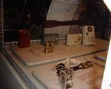
Intel 4004 microprocessor in 1971, from Intel Museum
Wozniak and Jobs introduced Apple II in 1977, from History of Apple
Apple I of 1976 , from Smithsonian NMAH
MITS Altair 8800A 1975 from
Apple II personal computer 1978 with 5.25-inch Disk drives, from SDCM - cu


Seagate ST-251 5-inch 40 MB hard drive 1978, from SDCM - cu


5. Fifth Generation (1991 and Beyond)

  • 1991 - World-Wide Web (WWW) was developed by Tim Berners-Lee and released by CERN.
  • 1993 - The first Web browser called Mosaic was created by student Marc Andreesen and programmer Eric Bina at NCSA in the first 3 months of 1993. The beta version 0.5 of X Mosaic for UNIX was released Jan. 23 1993 and was instant success. The PC and Mac versions of Mosaic followed quickly in 1993. Mosaic was the first software to interpret a new IMG tag, and to display graphics along with text. Berners-Lee objected to the IMG tag, considered it frivolous, but image display became one of the most used features of the Web. The Web grew fast because the infrastructure was already in place: the Internet, desktop PC, home modems connected to online services such as AOL and Compuserve
  • 1994 - Netscape Navigator 1.0 was released Dec. 1994, and was given away free, soon gaining 75% of world browser market.
  • 1996 - Microsoft failed to recognized the importance of the Web, but finally released the much imporoved browser Explorer 3.0 in the summer.
Nokia 9210 Communicator is part of the latest wave of web cell phones


world's first production microchips made of silicon-on-insulator (SOI) transistors and copper wiring by IBM (AP 5/22/00)


body scans to buy clothes
The raveMP player sells for $269 and can store more than an hour of MP3 music


digital insertion ads


wearable computers


History Of Computer


About L C D (Liquid Crystal Display)


LCD, What Is it?
A liquid crystal display (
LCD) is a thin, flat panel used for electronically displaying information such as text, images, and moving pictures. Its uses include monitors for computers, televisions, instrument panels, and other devices ranging from aircraft cockpit displays, to every-day consumer devices such as video players, gaming devices, clocks, watches, calculators, and telephones. Among its major features are its lightweight construction, its portability, and its ability to be produced in much larger screen sizes than are practical for the construction of cathode ray tube (CRT) display technology. Its low electrical power consumption enables it to be used in battery-powered electronic equipment. It is an electronically-modulated optical devicepixels filled with liquid crystals and arrayed in front of a light sourcebacklight) or reflector to produce images in color or monochrome. The earliest discoveries leading to the development of LCD technology date from 1888. By 2008, worldwide sales of televisions with LCD screens had surpassed the sale of CRT units.

Each pixel of an LCD typically consists of a layer of molecules aligned between two transparentelectrodes, and two polarizing filters, the axes of transmission of which are (in most of the cases) perpendicular to each other. With no actual liquid crystal between the polarizing filters, light passing through the first filter would be blocked by the second (crossed) polarizer.

The surface of the electrodes that are in contact with the liquid crystal material are treated so as to align the liquid crystal molecules in a particular direction. This treatment typically consists of a thin polymer layer that is unidirectionally rubbed using, for example, a cloth. The direction of the liquid crystal alignment is then defined by the direction of rubbing. Electrodes are made of a transparent conductor called Indium Tin Oxide (ITO).

Before applying an electric field, the orientation of the liquid crystal molecules is determined by the alignment at the surfaces of electrodes. In a twisted nematic device (still the most common liquid crystal device), the surface alignment directions at the two electrodes are perpendicular to each other, and so the molecules arrange themselves in a helical structure, or twist. This reduces the rotation of the polarization of the incident light, and the device appears grey. If the applied voltage is large enough, the liquid crystal molecules in the center of the layer are almost completely untwisted and the polarization of the incident light is not rotated as it passes through the liquid crystal layer. This light will then be mainly polarized perpendicular to the second filter, and thus be blocked and the pixel will appear black. By controlling the voltage applied across the liquid crystal layer in each pixel, light can be allowed to pass through in varying amounts thus constituting different levels of gray.

The optical effect of a twisted nematic device in the voltage-on state is far less dependent on variations in the device thickness than that in the voltage-off state. Because of this, these devices are usually operated between crossed polarizers such that they appear bright with no voltage (the eye is much more sensitive to variations in the dark state than the bright state). These devices can also be operated between parallel polarizers, in which case the bright and dark states are reversed. The voltage-off dark state in this configuration appears blotchy, however, because of small variations of thickness across the device.

Both the liquid crystal material and the alignment layer material contain ionic compounds. If an electric field of one particular polarity is a

pplied for a long period of time, this ionic material is attracted to the surfaces and degrades the device performance. This is avoided either by applying an alternating current or by reversing the polarity of the electric field as the device is addressed (the response of the liquid crystal layer is identical, regardless of the polarity of the applied field).

When a large number of pixels are needed in a display, it is not technically possible to drive each directly since then each pixel would require independent electrodes. Instead, the display is multiplexed. In a multiplexed display, electr

odes on one side of the display are grouped and wired together (typically in columns), and each group gets its own voltage source. On the other side, the electrodes are also grouped (typically in rows), with each group getting a voltage sink. The groups are designed so each pixel has a unique, unshared combination of source and sink. The electronics, or the software driving the electronics then turns on sinks in sequence,

and drives sources for the pixels of each sink.

Reflective twisted nematic liquid crystal display.

  1. Polarizing filter film with a vertical axis to polarize light as it enters.
  2. Glass substrate with ITO electrodes. The shapes of these electrodes will de termine the shapes that will appear when the LCD is turned ON. Vertical ridges etched on the surface are smooth.
  3. Twisted nematic liquid crystal.
  4. Glass substrate with common electrode film (ITO) with horizontal ridges to line up with the horizontal filter.
  5. Polarizing filter film with a horizontal a xis to block/pass light.
  6. Reflective surface to send light back to viewer. (In a backlit LCD, this layer is replaced with a light source.)

Specifications

Important factors to consider when evaluating an LCD monitor:

  • Resolution: The horizontal and vertical screen size expressed in pixels (e.g., 1024x768). Unlike CRT monitors, LCD monitors have a native-supported resolution for best display effect.
  • Dot pitch: The distance between the centers of two adjacent pixels. The smaller the dot pitch size, the less granularity is present, resulting in a sharper image. Dot pitch may be the same both vertically and horizontally, or different (less common).
  • Viewable size: The size of an LCD panel measured on the diagonal (more specifically known as active display area).
  • Response time: The minimum time necessary to change a pixel's color or brightness. Response time is also divided into rise and fall time. For LCD monitors, this is measured in btb (black to black) or gtg (gray to gray). These different types of measurements make comparison difficult. A r esponse time of <16ms id="cite_ref-0"> class="reference"> and the difference between response times below 10ms becomes imperceptible due to limitations of the human eye.
  • Refresh rate: The number of times per second in which the monitor draws the data it is being given. Since activated LCD pixels do not flash on/off between frames, LCD monitors exhibit no refresh-induce d flicker, no matter how low the refresh rate. Many high-end LCD televisions now have a 120 or 240 Hz (current and former NTSC countries) or 100 or 200 Hz (PAL/SECAM countries) refresh rate. The rate of 120 was chosen as the least common multiple of 24 frame/s (cinema) and 30 frame/s (NTSC TV), and allows for less distortion when movies are viewed due to the elimination of telecine (3:2 pulldown). For PAL at 25 frame/s, 100 or 200 Hz is used as a fractional compromise of the least common multiple of 600 (24 x 25). Until a 600 Hz refresh rate becomes available, PAL video will speed up cinema by a small percentage (current ly 1 to 4 percent). These higher refresh rates are most effective from a 24p-source video output (e.g. Blu-ray Disc), and/or scenes of fast motion.
  • Matrix type: Active TFT or Passive.
  • Viewing angle: (coll., more specifically known as viewing direction).
  • Color support: How many types of colors are supported (coll., more specifically known as color gamut).
  • Brightness: The amount of light emitted from the display (coll., more specifically known as luminance).
  • Contrast ratio: The ratio of the intensity of the brightest bright to the darkest dark.
  • Aspect ratio: The ratio of the width to the height (for example, 4:3, 5:4, 16:9 or 16:10).
  • Input ports (e.g., DVI, VGA, LVDS, DisplayPort, or even S-Video and HDMI).
  • Gamma correction
History Of LCD :
  • 1888: Friedrich Reinitzer (1858-1927) discovers the liquid crystalline nature of cholesterol extracted from carrots (that is, two melting points and generation of colors) and published his findings at a meeting of the Vienna Chemical Society on May 3, 1888 (F. Reinitzer: Beiträge zur Kenntniss des Cholesterins, Monatshefte für Chemie (Wien) 9, 421-441 (1888)).
  • 1904: Otto Lehmann publishes his work "Flüssige Kristalle" (Liquid Crystals).
  • 1911: Charles Mauguin first experiments of liquids crystals confined between plates in thin layers.
  • 1922: Georges Friedel describes the structure and properties of liquid crystals and classified them in 3 types (nematics, smectics and cholesterics).
  • 1962: The first major English language publication on the subject "Molecular Structure and Properties of Liquid Crystals", by Dr. George W. Gray.
  • 1962: Richard Williams of RCA found that liquid crystals had some interesting electro-optic characteristics and he realized an electro-optical effect by generating stripe-patterns in a thin layer of liquid crystal material by the application of a voltage. This effect is based on an electro-hydrodynamic instability forming what is now called “Williams domains” inside the liquid crystal.
  • 1964: George H. Heilmeier, then working in the RCA laboratories on the effect discovered by Williams realized the switching of colors by field-induced realignment of dichroic dyes in a homeotropically oriented liquid crystal. Practical problems with this new electro-optical effect made Heilmeier to continue work on scattering effects in liquid crystals and finally the realization of the first operational liquid crystal display based on what he called the dynamic scattering mode (DSM). Application of a voltage to a DSM display switches the initially clear transparent liquid crystal layer into a milky turbid state. DSM displays could be operated in transmissive and in reflective mode but they required a considerable current to flow for their operation.[8][9][10] George H. Heilmeier was inducted in the National Inventors Hall of Fame and credited with the invention of LCD.
  • 1960s: Pioneering work on liquid crystals was undertaken in the late 1960s by the UK's Royal Radar Establishment at Malvern, England. The team at RRE supported ongoing work by George Gray and his team at the University of Hull who ultimately discovered the cyanobiphenyl liquid crystals (which had correct stability and temperature properties for application in LCDs).
  • 1970: On December 4, 1970, the twisted nematic field effect in liquid crystals was filed for patent by Hoffmann-LaRoche in Switzerland, (Swiss patent No. 532 261) with Wolfgang Helfrich and Martin Schadt (then working for the Central Research Laboratories) listed as inventors. Hoffmann-La Roche then licensed the invention to the Swiss manufacturer Brown, Boveri & Cie who produced displays for wrist watches during the 1970s and also to Japanese electronics industry which soon produced the first digital quartz wrist watches with TN-LCDs and numerous other products. James Fergason while working with Sardari Arora and Alfred Saupe at Kent State University Liquid Crystal Institute filed an identical patent in the USA on April 22, 1971. In 1971 the company of Fergason ILIXCO (now LXD Incorporated) produced the first LCDs based on the TN-effect, which soon superseded the poor-quality DSM types due to improvements of lower operating voltages and lower power consumption.
  • 1972: The first active-matrix liquid crystal display panel was produced in the United States by T. Peter Brody.
  • 2007: In the 4Q of 2007 for the first time LCD televisions surpassed CRT units in worldwide sales.
  • 2008: LCD TVs become the majority with a 50% market share of the 200 million TVs forecast to ship globally in 2008 according to Display Bank.

A detailed description of the origins and the complex history of liquid crystal displays from the perspective of an insider during the early days has been published by Joseph A. Castellano in "Liquid Gold, The Story of Liquid Crystal Displays and the Creation of an Industry". Another report on the origins and history of LCD from a different perspective has been published by Hiroshi Kawamoto, available at the IEEE History Center.

Color displays


In color LCDs each individual pixel is divided into three cells, or subpixels, which are colored red, green, and blue, respectively, by additional filters (pigment filters, dye filters and metal oxide filters). Each subpixel can be controlled independently to yield thousands or millions of possible colors for each pixel. CRT monitors employ a similar 'subpixel' structures via phosphors, although the electron beam employed in CRTs do not hit exact 'subpixels'.

Color components may be arrayed in various pixel geometries,

depending on the monitor's usage. If the software knows which type of geometry is being used in a given LCD, this can be used to increase the apparent resolution of

the monitor through subpixel rendering. This technique is especially useful for text anti-aliasing.


To reduce smudging in a moving picture when pixels do not respond quickly enough to color changes, so-called pixel overdrive may be used.


Passive-matrix and active-matrix addressed LCDs

LCDs with a small number of segments, such as those used in digital watches and pocket calculators, have individual electrical contacts for each segment. An external dedicated circuit supplies an electric charge to control each segment. This display structure is unwieldy for more than a few display elements.

Small monochrome displays such as those found in personal organizers, or older laptop screens have a passive-matrix structure employing super-twisted nematic (STN) or double-layer STN (DSTN) technology—the latter of which addresses a color-shifting problem with the former—and color-STN (CSTN)—wherein color is added by using an internal filter. Each row or column of the display has a single electrical circuit. The pixels are addressed one at a time by row and column addresses. This type of display is called passive-matrix addressed because the pixel must retain its state between refreshes without the b

enefit of a steady electrical charge. As the number of pixels (and, correspondingly, columns and rows) increases, this type of display becomes less feasible. Very slow response times and poor contrast are typical of passive-matrix addressed LCDs.

High-resolution color displays such as modern LCD computer monitors and t

elevisions use an active matrix structure. A matrix of thin-film tran

A general purpose alphanumeric LCD, with two lines of 16 characters.

sistors (TFTs) is added to the polarizing and color filters. Each pixel has its own dedicated transistor, allowing each column line to access one pixel. When a row line is activated, all of the column lines are connected to a row of pixels and the correct voltage is driven onto all of the column lines. The row line is then deactivated and the next row line is activated. All of the row lines are activated in sequence during a refresh operation. Active-matrix addressed displays look "brighter" and "sharper" than passive-matrix addressed displays of the same size, and generally have quicker response times, p

roducing much better images.


Active matrix technologies


Twisted nematic (TN)

Twisted nematic displays contain liquid crystal elements which twist and untwist at varying degrees to allow light to pass through. When no voltage is applied to a TN liquid crystal cell, the light is polarized to pass through the cell. In proportion to the voltage applied, the LC cells twist up to 90 degrees changing the polarization and blocking the light's path. By properly adjusting the level of the voltage almost any grey level or transmission can be achieved.

In-plane switching (IPS)

In-plane switching is an LCD tec

hnology which aligns the liquid crystal cells in a horizontal direction. In this method, the electrical field is applied through each end of the crystal, but this requires two transistors for each pixel instead of the single transistor needed for a standard thin-film transistor (TFT) display. This results in blocking more transmission area, thus requiring a brighter backlight, which will consume more power, making this type

of display less desirable for notebook computers.

Advanced fringe field switching (AFFS)

Known as fringe field switching (FFS) until 2003, advanced fringe field switching is a similar technology to IPS or S-IPS offering superior performance and color gamut besides high luminosity. AFFS is developed by Boe Hydis Displays, Korea.

AFFS-applied notebook applications minimiz

e color distortion while maintaining its superior wide viewing angle for a professional display. Color shift and deviation caused by light leakage is corrected by optimizing the white gamut which also enhances white/grey reproduction.

As of 2008, Hitachi acquired AFFS license to manufacture high end panels in their product line. Boe Hydis suspended their production of high

quality displays; however, the company still advertises the benefits of the technology.

Vertical alignment (VA)

Vertical alignment displays are a form of LC displays in which the liquid crystal material naturally exists in a vertical state removing the need for extra transistors (as in IPS). When no voltage is applied, the liquid crystal cell remains perpendicular to the substrate creating a black display. When voltage is applied, the liquid crystal cells

shift to a horizontal position, parallel to the substrate, a

llowing light to pass through and create a white display. VA liquid crystal displays provide some of the same advantages as IPS panels, particularly an improved viewing angle and improved black level.

Blue Phase mode

Blue phase LCDs do not require an LC top layer. Blue phase LCDs are relatively new to the market,and very expensive because of the low volume

of production. They provide a higher refresh rate than normal LCDs, but normal LCDs are still cheaper to make and actually provide better colors and a sharper image.

Quality Control

Some LCD panels have defective transistors, causing permanently lit or unlit pixels which are commonly referred toas stuck pixels or dead pixels respectively. Unlike integrated circuits (ICs), LCD panels with a few defective pixels are usually still usable. It is economically prohibitive to discard a panel with just a few defective pixels because LCD panels are much larger than ICs. Manufacturers' policies for the acceptable number of defective pixels for vary greatly. At one point, Samsung held a zero-tolerance policy for LCD monitors sold in Korea.Currently, though, Samsung adheres to the less restrictive ISO 13406-2 standard. Other companies have been known to tolerate as many as 11 dead pixels in their policies. Dead pixel policies are often hotly debated between manufacturers and customers. To regulate the acceptability of defects and to protect the end user, ISO released the ISO 13406-2 standard. However, not every LCD manufacturer conforms to the ISO standard and the ISO standard is quite often interpreted in different ways.

LCD panels are more likely to have defects than most ICs due to their larger size. In the example to the right, a 300 mm SVGA LCD has 8 defects and a 150 mm wafer has only 3 defects. However, 134 of the 137 dies on the wafer will be acceptable, whereas rejection of the LCD panel would be a 0% yield. Due to competition between manufacturers quality control has been improved. An SVGA LCD panel with 4 defective pixels is usually considered defective and customers can request an exchange for a new one. Some manufacturers, notably in South Korea where some of the largest LCD panel manufacturers, such as LG, are located, now have "zero defective pixel guarantee", which is an extra screening process which can t

hen determine "A" and "B" grade panels. Many manufacturers would replace a product even with one defective pixel. Even where such guarantees do not exist, the location of defective pixels is important. A display with only a few defective pixels may be unacceptable if the defective pixels are near each other. Manufacturers may also relax their replacement criteria when defective pixels are in the center of the viewing area.

LCD panels also have defects known as mura, which look like a small-scale crack with very small changes in luminance or color. It is most visible in dark or black areas of displayed scenes. Defects in various LCD panel components can cause mura effect